Two decades ago, communication between a host computer and other devices was a complex and difficult task. The Universal Serial Bus (USB) was developed by a group of companies in 1994 to replace the multiple slow buses with a single bus that could exchange data between the host system and the peripherals. Following its release, USB quickly became very popular due to its ease of use and fast data transfer rate. Fast forward a little over two decades, all consumer electronic devices now come with integrated USB interfaces. The USB interface has evolved a lot to support modern demands of very high speed communication with host devices and their innovative features. Since its introduction, the USB specification has progressed as USB1.1, USB 2.0, USB 3.0, USB 3.1, USB 3.2 (Gen 1, Gen 2, Gen 2x2), USB Type-C supporting Thunderbolt, HDMI and DisplayPort via special modes, and finally, towards USB 4.

Even though successive versions of USB specifications cater to the needs of higher data rates and increased levels of power delivery, USB 2.0 still remains very popular among a multitude of electronic devices such as universal remotes, security panels, printers, cameras, speakers, medical devices, and of course, jump drives.
ESD Protection of USB 2.0 Interfaces
At this point, we need to consider an important electrical phenomenon called electrostatic discharge (ESD). A transfer of electrostatic energy between the host and peripherals may occur when we plug and unplug USBs. This may lead to an ESD event reaching thresholds of tens of thousands of volts. ESD can lead to damage of the delicate internal circuitry of the host or peripheral transceiver. ESD protection is achieved by placing a transient voltage suppression (TVS) diode between the USB port and the USB controller. Ideally, the TVS diode is placed as closely as possible to the USB port to arrest the transient threat as close as possible to the source.
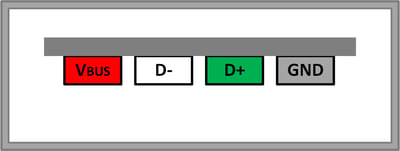 Figure 1. Pin Configurations of USB 2.0
As shown in Figure 1, USB 2.0 has a 4-wire interface. VBUS provides 5V and 500mA power from the host to the attached device via a cable. D+ and D- pins are responsible for carrying a differential data signal. The voltages on these differential lines can reach up to 5V under normal operating conditions. The fourth pin is the GND pin, also called the reference pin. USB 2.0 supports the following data speeds:
- Low Speed – 1.5Mbps
- Full Speed – 12Mbps
- High Speed – 480Mbps
VBUS provides 5V and 500mA power through the USB cable to the attached device. The TVS diode should feature a fast response time to clamp transient voltages during ESD events immediately before it can damage a circuit. It should also feature low clamping voltage, high surge current capability and no device degradation during the protection of the VBUS pin. The low clamping voltage is essential. The TVS diode should be connected in parallel with the USB controller circuit. During an ESD event, TVS diodes protect USB ports by diverting the high current away from the port through the low resistance TVS path. That effectively clamps high voltage peaks and helps avoid system damage. Under normal operating conditions, the TVS diode presents a high impedance path to the protected circuit, so the device appears as an open circuit and essentially appears electrically transparent to the system interface. However, this low resistance path is not entirely resistance-free. There is a small dynamic resistance across the diode. We can find the dynamic resistance from the current-voltage relationship TLP plots on the datasheet of the TVS diodes. Referring to the slope of the TLP curve, we can see that the dynamic resistance as well as the clamping voltage values are very small. The sharper the slope of the current-voltage characteristic curve, the more efficient the TVS device is clamping. Since the TVS diode and the USB controller are connected in parallel, the voltage drop across the USB controller is the same as the clamping voltage of the TVS diode during an ESD event. So it is vital to keep the clamping voltage as small as possible.
There are two different common configurations employed to protect the USB 2.0 port from ESD threats. Separate discrete TVS diodes can be used to protect the VBUS and the D+/D- lines separately, or an integrated TVS array in a single chip can be used to protect all three lines.

Using Discrete TVS Diodes to Protect USB 2.0 Interfaces
In the first option, Semtech’s µClamp®0571P meets all the criteria and is a worthy candidate to protect USB 2.0 VBUS pin. µClamp0571P features 5V operating voltage with high surge peak current capability of 80A. It comes in a 1.6 x 1.0 x 0.5mm package size. Figure 2 shows the connection diagram of TVS protection at the USB 2.0 port.
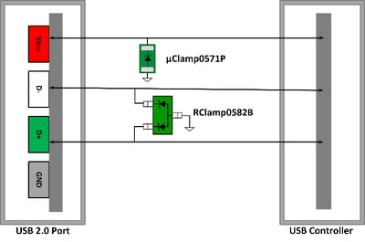 Figure 2. ESD Protection of USB 2.0 Port Using Discrete TVS Diodes
D+ and D- pins carry a differential 480 Mbps data signal. Since they are high-speed differential data lines, TVS diodes should protect the USB port and the circuit during transient events while ensuring signal integrity by maintaining a low line-to-line capacitance. Semtech’s RClamp®0582B, a dual-channel device, can be used to protect D+ and D- lines. RClamp0582B provides transient protection as per the specification in IEC 61000-4-2 (ESD) at ±30kV (Air) and ±30kV (Contact). It is built in the industry standard SOT-523 package. The maximum junction capacitance of RClamp0582B is extremely low, only 1.2pF, and offers a dynamic resistance of 0.52Ω (Typical).
Using a Single TVS Diode to Protect USB 2.0 Interfaces
Now let us discuss the second type of ESD protection, provided by using a single integrated TVS device. Semtech’s RClamp7522T is a 5V TVS protection solution for VBUS and D+/D- pins altogether. The RClamp7522T has a maximum capacitance of 0.4pF between any line and ground while being rated to handle ±25kV (Air) and ±15kV (Contact). This meets the specification as per IEC 61000-4-2 standard, and is offered in a 5-pin package with a nominal dimension of 1.0 x 0.7 x 0.4 mm. Figure 3 below shows the connection diagram for TVS protection between the USB 2.0 port and the controller.
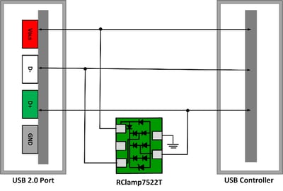 Figure 3. ESD Protection for USB 2.0 Port with RClamp7522T
Combination of EMI Filter and ESD Protection
The discussion of ESD protection of USB 2.0 interfaces would not be complete if we do not mention another challenge called electromagnetic interference (EMI). EMI is the interference in operation of an electrical circuit caused by emission in the radio frequency (RF) spectrum from an external source. EMI interference can be avoided using an EMI filter that eliminates the unwanted RF noise while maintaining signal integrity. EMI filters with integrated ESD protection can be used to filter this RF noise as well as prevent electrostatic discharges. Semtech’s EClamp®8052P, shown in Figure 4, is an exceptional solution to protect D+ and D- lines against ESD and EMI in USB 2.0 interfaces. It uses a 2-line integrated common mode filter and an ESD protection device. The integrated common-mode filter has a typical differential mode cutoff frequency greater than 3GHz. EClamp8052P also features the typical common mode suppression of 10dB at 500MHz and 15dB from 1GHz to 2.8GHz. It has a maximum channel capacitance of 1.2pF while being rated to handle ±30kV (Air) and ±25kV (Contact) per the IEC 61000-4-2 specification.
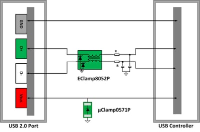 Figure 4. EMI and ESD Protection of USB 2.0 Port
Summary and Conclusion
The USB 2.0 interface is still immensely popular among consumer, non-handheld, industrial, medical, and storage devices. An average person connects at least three to four peripheral devices to his or her computer every day using USB 2.0 interfaces. Protecting the USB 2.0 ports from disastrous ESD events is mandatory. No user would like to experience damage to his or her electronic equipment due to an ESD event triggered through the USB interface. Semtech’s wide range of TVS diodes protect many of the world’s most popular electronics devices. Its highly efficient and trusted TVS products protect all types of USB interfaces including USB 2.0. You can enjoy problem-free, glitch-free data transmission by protecting your USB 2.0 ports with Semtech TVS diodes, while also enhancing the reliability and lifetime of the protected devices.

Semtech®, the Semtech logo, EClamp®, RClamp®, and μClamp® are registered trademarks or service marks of Semtech Corporation or its affiliates. Other product or service names mentioned herein may be the trademarks of their respective owners.