LoRa®による長距離
How do we increase the range of a radio link? Here we look at the constraints at work when building a real-world long range radio link. We’ll show how and why LoRa Technology is the right choice for designing a radio link where range matters.
Long Range and Low Consumption in the Real World
How do we maximize the range of a low power radio link in a practical application? Assuming that we do not want to incur the hardware and recurring operating costs together with the high energy consumption of a Cellular solution, this means finding a solution in the license-free ISM band.
How to Make a Long Range RadioLink?

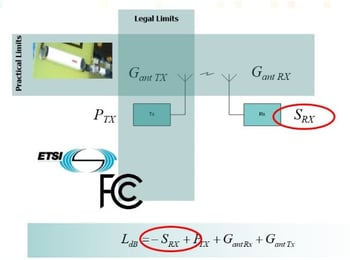
The picture above shows the real-world constraints imposed on a radio design. Here we’ll just consider a one-way link for simplicity, with a single transmitter, Tx and a receiver, Rx each connected to an antenna with gain, G.To improve the range of the link we need to consider the two fundamental constraints at work here:
Regulatory Limits
These are the legal limits for operating a radio. These vary between jurisdictions, but if we look at the EU (ETSI) and US (FCC) regulations as a guide, the most important constraint that limits range is that transmitted power (PTX) above a certain level is not permitted. High power transmission also implies high power consumption – so is not necessarily desirable in the first place.
Practical Limits
It is possible that we could increase the size and gain of the receiver antenna to augment our range, but the link needs to be suitable for the application. This ordinarily puts significant practical limitations on the size and gain of the antenna.
Given the combination of regulatory and practical constraints faced in designing a long range link, this leaves us with only the receiver sensitivity as the area where we are free to maximize our range.
Maximizing Sensitivity for Long Range Communication
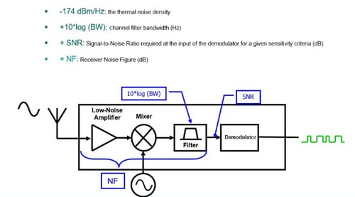
Looking at the receiver shown below, we see the main elements present in almost every low power radio design today.
LNA
The signal arrives first at the Low Noise Amplifier, LNA. The role of the LNA is to amplify the signal, adding as little noise as possible. Every real amplifier adds noise. We use the noise figure, NF, as a measure of the noise added during the amplification process.
Mixer
The mixer down-converts the amplified signal to a lower baseband or intermediate frequency, where the signal can be processed more easily by simpler, lower frequency electronics than at radio frequency.
Channel Filter
The channel filter limits the frequencies ‘seen’ by the following stages. What is important here is that this also limits the thermal noise. Thermal noise is the electrical noise generated by all electronics which in radio systems, is expressed as a noise power density (kTB noise). Here k is Boltzmann’s constant, T is temperature and B is the bandwidth. In dB units at 25°C this equates to -174 dBm/Hz. For every Hz of channel filter (receiver) bandwidth, BW, we sum more of this noise power. Staying in decibels, the thermal noise power added is given by -174 + 10 * log10(BW).

Demodulator
Finally, we have the demodulator. This is where the received signal is converted (in our case) to a digital output. The demodulator can function down to a certain signal to noise ratio (SNR). Below this level the signal can either no longer be demodulated or will incur more errors.
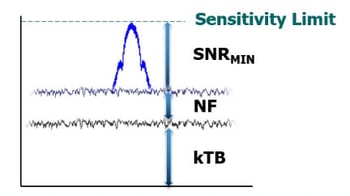
The sum of all of these terms gives us our theoretical sensitivity expressed as an absolute power in dBm. This is shown graphically below:

If we want to increase our sensitivity, we must improve one of these parameters. Arguably the most effective way of doing this is to drastically reduce the SNR requirement at the demodulator input by using spread spectrum.
Spread Spectrum & Negative SNR
Spread spectrum is a technique that involves translating a low data rate signal and ‘spreading’ it over a wider frequency spectrum. Translating a low data rate signal to a wider band signal does increase the bandwidth (BW above) of our signal. However, with knowledge of the wider band signal used in the spreading process, it is possible for the receiver to correlate and ‘de-spread’ the spread spectrum signal with a negative signal to noise ratio, i.e. signals can be recovered from below the thermal noise.
Long Range with LoRa Spread Spectrum
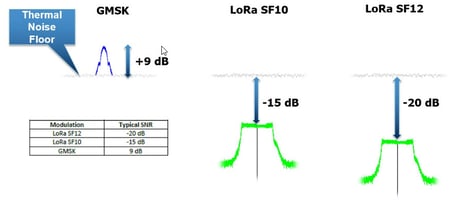
This phenomenon is shown below. LoRa modulation uses wideband frequency chirp to spread and encode the input data. The benefit of LoRa spread spectrum is the ability to receive up to 20 dB below the thermal noise floor. Note that as we increase sensitivity we are obliged to send data at lower and lower effective data rates, increasing our time on air. The figure below shows this effect in action. In the same bandwidth we see the positive SNR required for MSK modulation compared with LoRa spreading factors (data rates) of SF10 and SF12.

This performance gives us the ability to choose between data rate and sensitivity in our application software. With no data rate or time-on-air penalty we win 8 dB of additional sensitivity compared with legacy modulation schemes - just by switching to LoRa modulation. Alternatively, we can transfer data at a lower data rate and benefit from even higher sensitivities and establish connections that would not have otherwise been possible.
Conclusion
Here we’ve seen that receiver sensitivity can be improved without any regulatory restriction and that spread spectrum allows us to improve the sensitivity of the receiver by receiving below the thermal noise. In the case of LoRa, using chirp spread spectrum, the receiver sensitivity can be increased by 8 dB with no additional energy consumption.
What Next?
For a quick overview of designing with the LoRa modem please check out my Application Note on designing with the LoRa modem. To get more information on the specifics of the LoRa modem and how to optimise the consumption then please take a look at low power designer’s guide.